

FAQ
General
 Services
Zip-Bit Inc. provides the following services -
- Rapid Prototyping
- 3D Scanning(Structured Light & LASER)
- Parametric Modeling
- 3D Printing
- CAD File Conversions
- Consulting Software
- Perl (tools, scripts, CGI, mod_perl, etc...)
- UNIX/Linux (system support, implementation)
- QA Automation (UNIX/Linux system architecture, implementation, support)
- Consulting Hardware (Electronic)
- Parallax Propeller design/programing
- R/C servo design
- Automation
CapabilitiesThe following equipment is used in house for Rapid Prototyping -
- Hardware
- RadiusEX super computer graphics workstation by NextComputing
- COMET L3D 5M by Zeiss-Steinbichler Optotechnik
- GO!SCAN3D by Creaform
- HDI Advance R2 by LMI (formerly 3D3 Solution)
- 3D Laser Scanner Ultra HD by NextEngine
- Dimension SST 1200es 3D Printer by Dimension 3D Printers
- Sherline 4400-CNC Lathe Sherline
- Sherline 2000-CNC 8 axis Mill Sherline
- Sherline 8730 4th or "A" axis rotary table w/programmable controller Sherline
- Software
- Gromagics Design X by 3D Systems
- ScanStudio HD PRO (64 bit) NextEngine
- ScanStudio CAD TOOLS (64 bit) NextEngine
- RapidWorks (64 bit) "Rapidform's XOR bundled for NextEgnine" NextEngine
- SolidWorks 2009 - 2016 "premium" (64 bit) Dassault Systems SolidWorks Corp
- Magics RP (64 bit) Materialise
- Rhino 4.0 McNeel
- Global Mapper Global Mapper Software LLC
- AcuTrans 3D MicroMouse Productions
- netfabb Studio Professional netfabb
- Protean Protean
- Geomagics Design (formerly Alibre) 3D Systems
3D Scanning (Laser & Structured Light)
3D Structured Light Scanners | |
|---|---|
| Creaform | Go!SCAN 3D |
| Weight | 1.1 kg (2.4 lbs.) |
| Dimensions | 127 x 156 x 262 mm (5 x 6.2 x 10.3 in.) |
| Light Source | White light (LED) |
| Measurement Rate | 550,000 measures /sec. |
| Resolution | 0.500 mm (0.020 in.) |
| Accuracy | Up to 0.100 mm (0.004 in.) |
| Volumetric Accuracy* | 0.300 mm/m (0.0036 in./ft) |
| Stand-Off Distance | 400 mm (15.75 in.) |
| Depth-of-field | 250 mm (10 in.) |
| Scanning Area | 380 mm x 380 mm (15 in. x 15 in.) |
| Software | VXelements2 |
| Output Format | .dae, .fbx, .ma, .obj, .ply, .stl, .txt, .wrl, .x3d, .x3dz, .zpr |
| Connection Standard | 1 x USB 2.0 |
| Part size range (recommended) | 0.3 m – 3.0 m (1 ft – 10 ft) |
|
* With positioning targets or with an object presenting sufficient geometry for positioning. |
|
| 3D3 Solutions | HDI ADVANCE R2 |
| Object Size | No preset limit. Objects larger than field may be composite captured with supplied software. |
| Cameras | Two 5MP high-speed machine vision cameras (CCD sensor, FireWire) |
| Lens | Two 5MP 12.5mm lens |
| Accuracy 3D Point Distance at 200mm diagonal field of view (average) | 30æm (standard deviation 35æm) 0.0012" (standard deviation: 0.0014") |
| Accuracy 3D Point Distance at 300mm diagonal field of view (average) | 50æm (standard deviation 60æm) 0.002" (standard deviation: 0.0024") |
| Camera Resolution | 2048 x 1536 |
| Average Points | 1.7 million per scan |
| Average Polygons | 3.5 million per scan |
| Sensor | Black and White (Monochrome) |
| Scan Speed | 1.4 seconds |
| Point to Point Distance (200mm diagonal field of view) |
0.16mm |
| Field of View Fixed | 300mm diagonal |
| Adjustable | 20mm to 2000mm diagonal |
| Geometry Formats | PLY, OBJ, STL, ASC, 3D3 |
| DAVID Vision System GmbH | DAVID SLS-1 (3D Structured Light Scanner) |
| Scan Object Sizes | 10mm - 600mm |
| Accuracy | ~0.1% of object size |
| Single Scan Time | 2-4s |
| Handling / Comfort | +++ |
| Mobility | +++ (scanner on tripod) |
| Texturing | yes (color) |
|
3D LASER Scanners | |
| NextEngine 3D Laser Scanner HD | |
| Object Size | No preset limit. Objects larger than field can be composite captured with supplied software. |
| Field Size | 5.1" x 3.8" (Macro mode) and 13.5" x 10.1" (Wide mode) |
| Texture Density | 400 samples (points) per inch in (Macro mode) and 150 samples per inch in (Wide mode) |
| Dimensional Accuracy | +- 0.005" in (Macro mode) and +- 0.015" in (Wide mode) |
| Acquisition Speed | 50,000 points/sec throughput, two minute per scan of each facet |
| Datasets | Typical small models are 250,000 points after processing |
| File Size | 20 MB for typical full color model with textures based on a ten facet scan |
| RapidWorks | Software for the NextEngine Scanner HD (INUS/Rapidform's XOR3 bundled for NextEngine) |
|
For its 3D desktop scanner, NextEngine offers two software packages to edit/modify the acquired 3D Scan datum, it's own ScanStudio PRO and RapidWorks software (this is a full blown version of INUS Rapidform XOR3 bundled to work only with the NextEngine). While ScanStudio PRO can export splines and NURBS representations of your model, RapidWorks generated CAD models include editable sketches and a full feature tree. At all steps in the process, the 3D scan datum acts as a guide, and the software snaps to the 3D scan datum and automatically recognizes features of interest. While you work, built in accuracy checking makes sure your design is faithful to the original. RapidWorks is a hybrid modeler; it has full support for both solid modeling and surface modeling. Surfaces are a powerful way to represent complex curved and organic shapes. The software can recognize many features, including: revolutions, extrusions, planes, freeform areas, and many primitives. While you're creating sketches and solids, this knowledge is used to provide intelligent snapping. For example, when extruding a sketch, the software will automatically extend the extrusion to the right point. If you're creating a fillet, it uses the scan data to automatically determine the proper radius and fillet type. |
|
| DAVID Vision System GmbH | DAVID Starter-Kit (3D LASER Scanner) |
| Scan Object Sizes | 10mm - 400mm |
| Accuracy | ~0.5% of object size |
| Single Scan Time | ~40s |
| Handling / Comfort | + |
| Mobility | + (modular setup) |
| Texturing | yes (color) |
3D FDM Printing| 3D Printer | Dimension SST 1200 |
| Model material: | ABS acrylonitrile butadiene styrene (chemical formula (C8H8)x'(C4H6)y'C3H3N)z) is a common, strong, durable production-grade thermoplastic used across many industries.
ABS is an ideal material for conceptual prototyping through design verification through direct digital manufacturing. This material is ideal for the rapid production of prototypes, tooling and the direct (tool-less) manufacturing of production parts. ABS is widely used in applications where impact-resistance and structural strength are necessary. It is accurate, durable and robust enough for field testing or demonstration units. Because of its excellent dimensional stability, it is ideal for pre-production rapid prototypes that can accurately predict performance of injection molded parts. |
| ABS: colors | black, blue, yellow, gray, green, ivory, orange, olive red, white |
| Support material: | Soluble Support Technology (SST) |
| Material Cartridges: | One autoload cartridge with 922 cu. cm. (56.3 cu. in.) ABS material. One autoload cartridge with 922 cu. cm. (56.3 cu. in.) support material. |
| Layer Thickness: | 254 mm (.010 in.) or .33 mm. (.013 in.) of precisely deposited ABS model and support material. |
| Build Size: | 254 x 254 x 305 mm (10 x 10 x 12 inches) |
| Regulatory Compliance: | CE / ETL |
|
Based on the patented Stratasys FDM®, Dimension builds functional 3D models from the bottom up, one layer at a time of with tough, ABS plastic. STL files are imported into CatalystEX® software which automatically slices and orients the parts and creates any necessary support structures. The software automatically plots a precise deposition path for Dimension to follow. ABS plastic (in filament form within auto-loading cartridges) is fed into an extrusion head, heated to a semi-liquid state and accurately deposited in layers as fine as 0.010-inch (0.254 mm) thick. After completion of the build, support structures are simply removed. |
|
|
|
|
 |
|
|
ABS plastic is heated to a semi-liquid state and deposited in thin layers by a patented extrusion head.
|
|
 |
|
|
Catalsyt software automatically determines when and where to deposit ABS or support material throughout the build process.
|
|
3D SLA Printing| generic 3D SLA (Stereolithography) Printing |
|
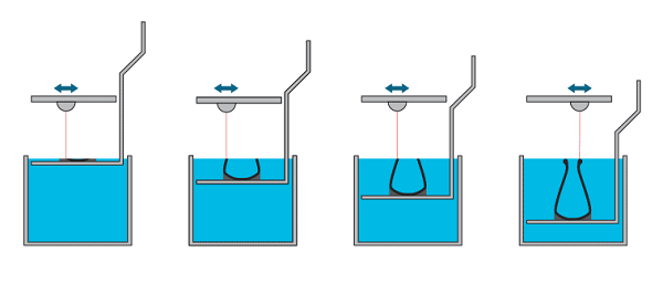
Stereolithography, the technology behind most resin 3D prints, is often referred to as ‘the mother of all 3D printing technologies’ and is considered one of the most widely used techniques for producing high-quality 3D prints. Stereolithography printers work with razor-thin layers of liquid polymer that are cured by a computer-controlled UV laser which transforms the resin from a liquid to a solid state.
|
 |
|
for more information please see https://i.materialise.com/3d-printing-technologies/stereolithography
|
3D Printer Input File Formats |
|
Parametric Modeling| Basic Scan Data Outputs | |
|---|---|
| Point Cloud (.asc, .txt): | Point Cloud data is often the most basic scan data output, and mostly used for downstream applications. This data is not easily imported into most CAD/CAM packages. |
| Polymesh (.stl) | A conversion from the point cloud into a triangulated surface mesh. In special cases a polymesh file can be used directly for 3D printing or machining of organic shapes. |
| CAD Modeling Outputs | |
| Surface (NURBS) Model (.igs, .stp) | A freeform CAD model defined by spline-based surfaces (NURBS). These models only match the as-built state of the part and are ideal for curvature, but not sharp features. |
| Solid Model (.igs, .stp, .x_t, .x_b) | A feature-based CAD model without a design history. These models can either incorporate or fix manufacturing defects and are ideal for prismatic shapes and sharp edges. |
| Hybrid Model (.igs, .stp) | A combination of imported surfaces and CAD features. These models are ideal for parts with a mixture of prismatic features and complex curvature or organic geometry. Parametric Model (Solidworks, Pro/E, Catia, etc.) The ultimate CAD model that maximizes editability and performance by incorporating a design history tree and dimensioning. Ideal for when changes to the model are needed. |
| Organized Polymesh (.stl, .obj, .ply) | A conversion from a CAD model to a polymesh. The size and spacing of the triangles are organized, resulting in a higher quality mesh that is ideal for rendering and animation. |
| Class A Surface Model (.igs, .stp) | Typically a Surface Model whose surfaces are all curvature-continuous and tangent. This is important to allow for an ideal aesthetic look and feel, especially in reflections. |
| Block Model (.igs, .stp) | A block model can be created in situations where the level of detail is not a high priority. For example, the wheels in a car assembly can be cylinders for location and reference. |
Clean & Optimized Polygon Mesh / Point Cloud -
Data is processed from single or multiple scans. Geometry is represented by a mesh of triangles Holes have been filled, defects removed, rough spots smoothed. Suitable for CNC machining, rapid prototyping, 3D printing or further processing into a surface or solid model.
File Format: stl
Cross-Sectional Curves -
Network of curves developed by slicing through a point cloud or polygonal mesh. Geometry is represented by splines. Useful for import into CAD to develop 2D drawings or 3D models.
File Format: iges
Rapid Surface Model -
Quilt of smooth surface patches is "shrink-wrapped" onto the polygonal mesh to create a model suitable for import into CAD. Upon CAD import, surfaces are knit together to form a static, or non-parametric solid. Useful for highly complex shapes such as organic forms, art & sculpture or intricate castings.
File Format: iges, step, Solidworks (sldprt)
Feature Based Solid Model -
Model is composed of primitive geometric features, trimmed surfaces, fillets & radii. Geometry is developed using traditional solid modeling techniques such as sketching and extruding, using the underlying scanned data as a reference. Original feature geometry may be extracted after import into customer CAD system.
File Format: iges, step, parasolid, Solidworks (sldprt)
Parametric Solid Model -
Model is composed of primitive geometric features, trimmed surfaces, fillets & radii. Geometry is developed using traditional solid modeling techniques such as sketching and extruding, using the underlying scanned data as a reference. Entire model history is transferred into Solidworks upon completion in order to facilitate future design changes.
File Format: Solidworks (sldprt)
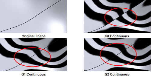
| G0 (Positional continuity) | Holds whenever the end positions of two curves or surfaces are coincidental. The curves or surfaces may still meet at an angle, giving rise to a sharp corner or edge and causing broken highlights. |
| G1 (Tangential continuity) | Requires the end vectors of the curves or surfaces to be parallel, ruling out sharp edges. Because highlights falling on a tangentially continuous edge are always continuous and thus look natural, this level of continuity can often be sufficient. |
| G2 (Curvature continuity) | Further requires the end vectors to be of the same length and rate of length change. Highlights falling on a curvature-continuous edge do not display any change, causing the two surfaces to appear as one. This can be visually recognized as "perfectly smooth". This level of continuity is very useful in the creation of models that require many bi-cubic patches composing one continuous surface. |
 |
|
3D Modeling Examples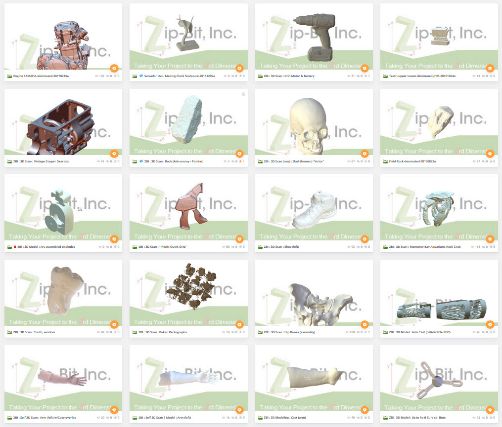
Zip-Bit is one of the nation’s few independent, full-service providers of 3D Engineering Services, 3D Digitizing and 3D Printing Services